Make sure that your stock matches the material. These sheets are exact only for
this material size. One 2.8 mm kerf is used for every piece.
The first 8 stock lengths release all
twenty-three 1 175 blanks. Fourteen side boards come first, then nine
door boards, at one stop setting.
Operation A · release every 1 175 blank
Stock
Codes, cut in this order
Available after the batch
P01
LSC1LSC2LSC3
966.6 · keep for 397
P02
LSC4LSC5LSC6
966.6 · keep for 397
P03
LSC7RSC1RSC2
966.6 · keep for 397
P04
RSC3RSC4RSC5
966.6 · terminal offcut
P05
RSC6RSC7DCB1
966.6 · terminal offcut
P06
DCB2DCB3DCB4
966.6 · terminal offcut
P07
DCB5DCB6DCB7
966.6 · terminal offcut
P08
DCB8DCB9
2 144.4 · keep for 1 050
Set the stop once. Cut all twenty-three blanks from P01 onward. Mark each code
immediately. When a stock length ends, continue at the same setting on the next one.
Label the P01 to P03 remainders. Keep them for the final 397 pass.
Move every marked blank to its unit stack. Do not join or trim loose cladding.
Operation B · cut the remaining pieces
Change the stop only once per row. Cut every piece in that row, then move to the
next stop. The final 397 row uses the labeled
P01 / P02 / P03 remainders.
Batch order · A-300 operation B
Pass
Stop
Saw setup
Mark these pieces
1
1 050
90° square
8 × BWC1BWC2BWC3BWC4BWC5BWC6BWC7BWC8
2
747
90° square
8 × FCB1FCB2FCB3FCB4FCB5FCB6FCB7FCB8
3
500
90° square
8 × STB1STB2STB3STB4STB5STB6STB7STB8
4
397
90° square
8 × SFB1SFB2SFB3SFB4SFB5SFB6SFB7SFB8
5 pieces
LSC11 175
LSC21 175
LSC31 175
SFB1397
SFB2397
167
5 pieces
LSC41 175
LSC51 175
LSC61 175
SFB3397
SFB4397
167
5 pieces
LSC71 175
RSC11 175
RSC21 175
SFB5397
SFB6397
167
3 pieces
RSC31 175
RSC41 175
RSC51 175
966.6
3 pieces
RSC61 175
RSC71 175
DCB11 175
966.6
3 pieces
DCB21 175
DCB31 175
DCB41 175
966.6
3 pieces
DCB51 175
DCB61 175
DCB71 175
966.6
4 pieces
DCB81 175
DCB91 175
BWC11 050
BWC21 050
38.8
4 pieces
BWC31 050
BWC41 050
BWC51 050
BWC61 050
288.8
5 pieces
BWC71 050
BWC81 050
FCB1747
FCB2747
FCB3747
145
6 pieces
FCB4747
FCB5747
FCB6747
FCB7747
FCB8747
STB1500
248.2
9 pieces
STB2500
STB3500
STB4500
STB5500
STB6500
STB7500
STB8500
SFB7397
SFB8397
180.8
Do not trim loose cladding
Gaps between boards change the joined width. Fix each board to its unit frame before
you mark any final edge.
Use the frame edge to set the circular-saw guide. Cut only after the boards are fixed.
Sheet A-400 shows each estimated overhang and cut line.
Sheet A-400
Unit drawings and assembly
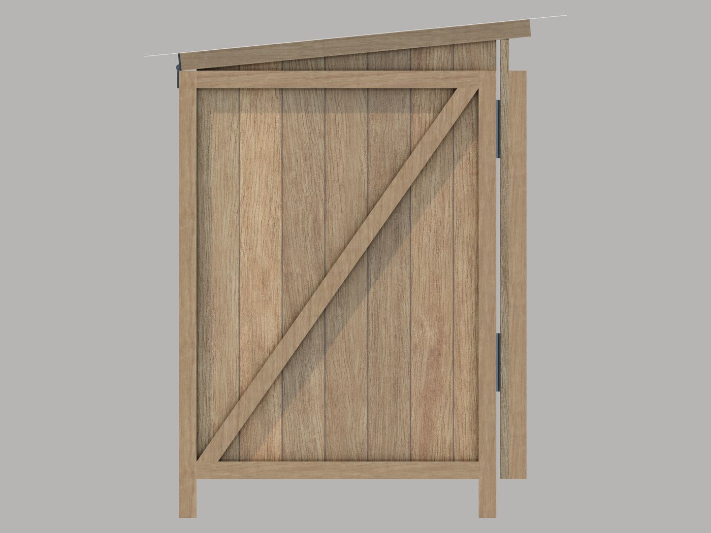
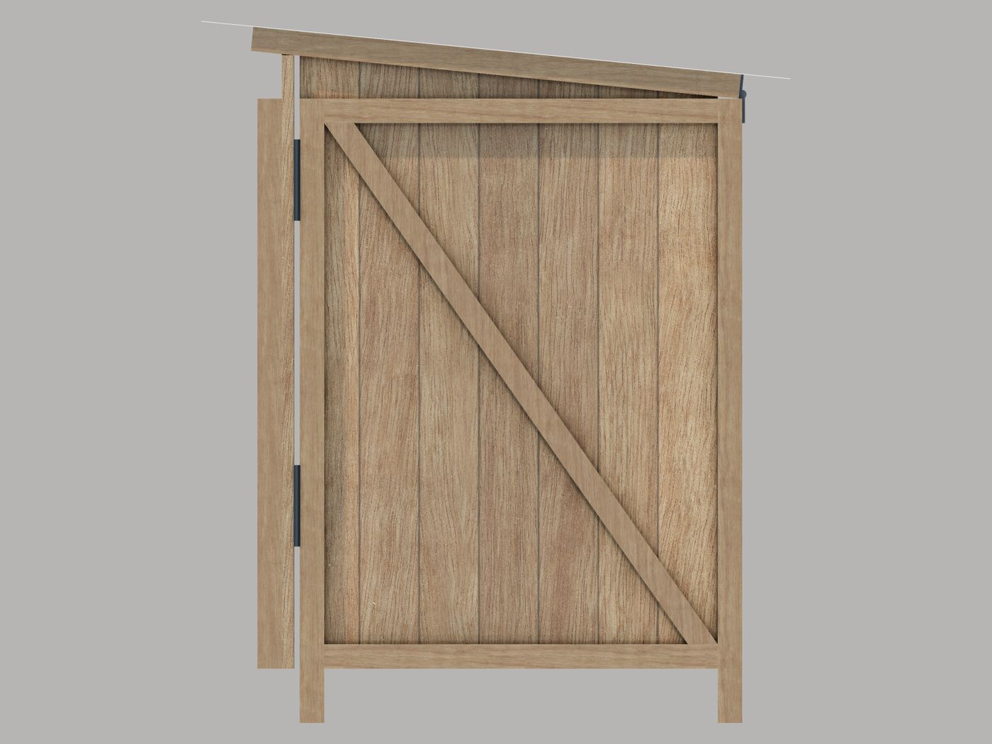
Each drawing is an orthographic projection off the model. Solid
members are the frame. Tinted fields are cladding. Hatching shows the nominal material
left for an on-frame cut.
Use the Frame and Cladding controls to change drawing emphasis.
The printed drawing keeps every cut line, trim label, and notch note visible.
Stack A
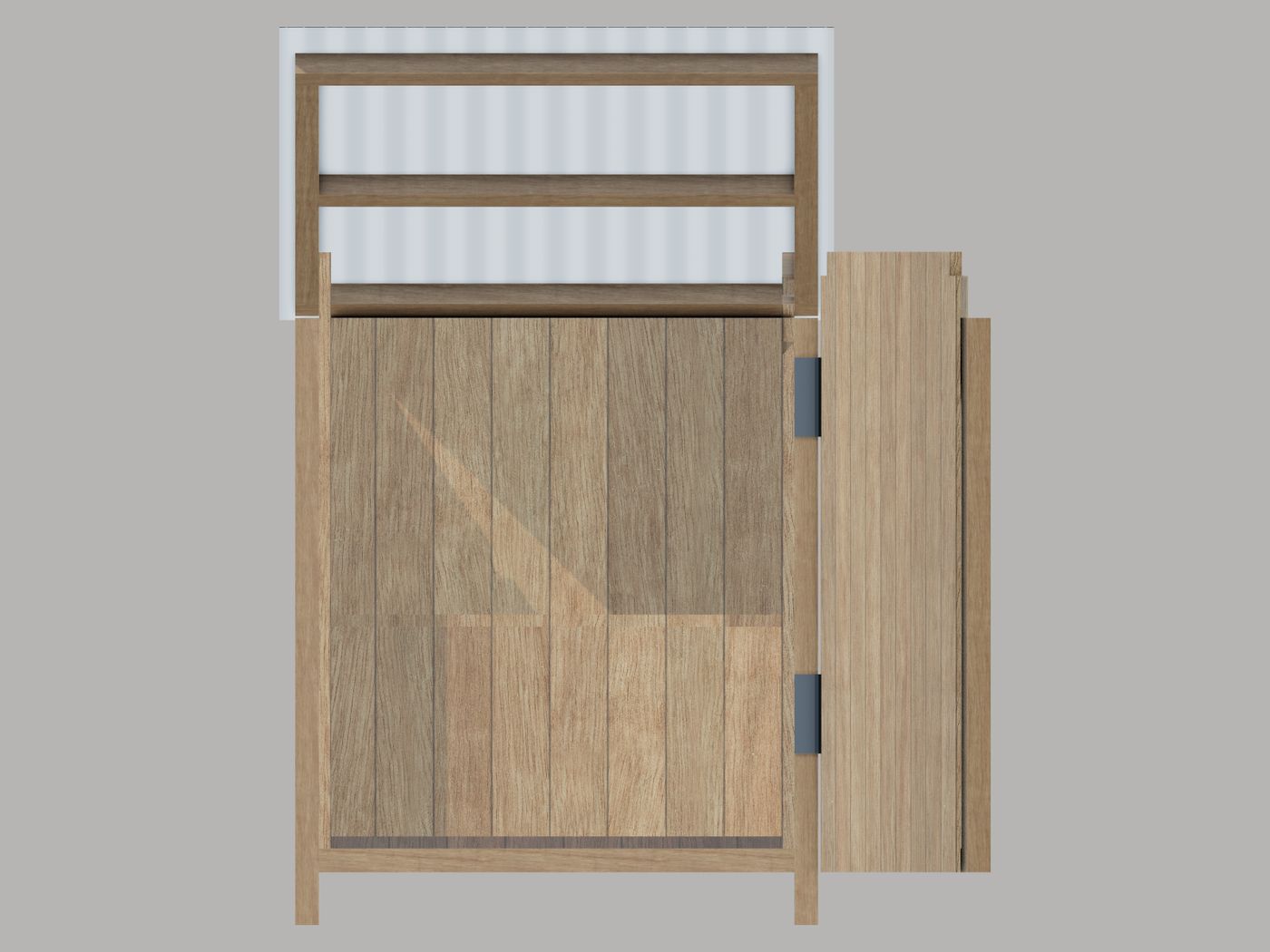
Roof unit
ROOF UNITA-401 · PLANfront edge at the bottom · built flat, then hung
Assembly
Lay RBH1 and RBH2 around RBS1 and RBS2. Center RBC1. Match the diagonals, then fasten the frame.
Center the metal sheet with 30 at each side and 93.1 at the front and rear.
Fit the moving hinge leaf. After the shell is square, fit the fixed leaf and hang the roof.
RBC1RBH1RBH2RBS1RBS2
Stack B
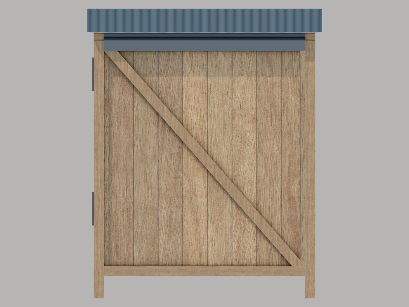
Door unit
DOOR UNITA-402 · FRONT ELEVATIONseen from outside the door · hatched edge is the estimated on-frame trim
Assembly
Build the DBV and DBH frame. Fit DBD1 and match the diagonals.
Fix DCB1 to DCB9 on the inside face. Align DCB1 with the left frame edge.
Use the right frame edge to set the circular-saw guide. Cut the estimated 10 overhang after the boards are fixed.
Cut the two top reliefs shown. Fit the moving hinge leaves, then hang the door with a 10 gap after the shell is square.